
With a warm engine, turn OFF the ignition key, and then set it to ON.

But don't take my word on this, cause I love to be proven wrong, do this test instead, It'll continue to give the ECU the same information irregardless of power source fluctuations.

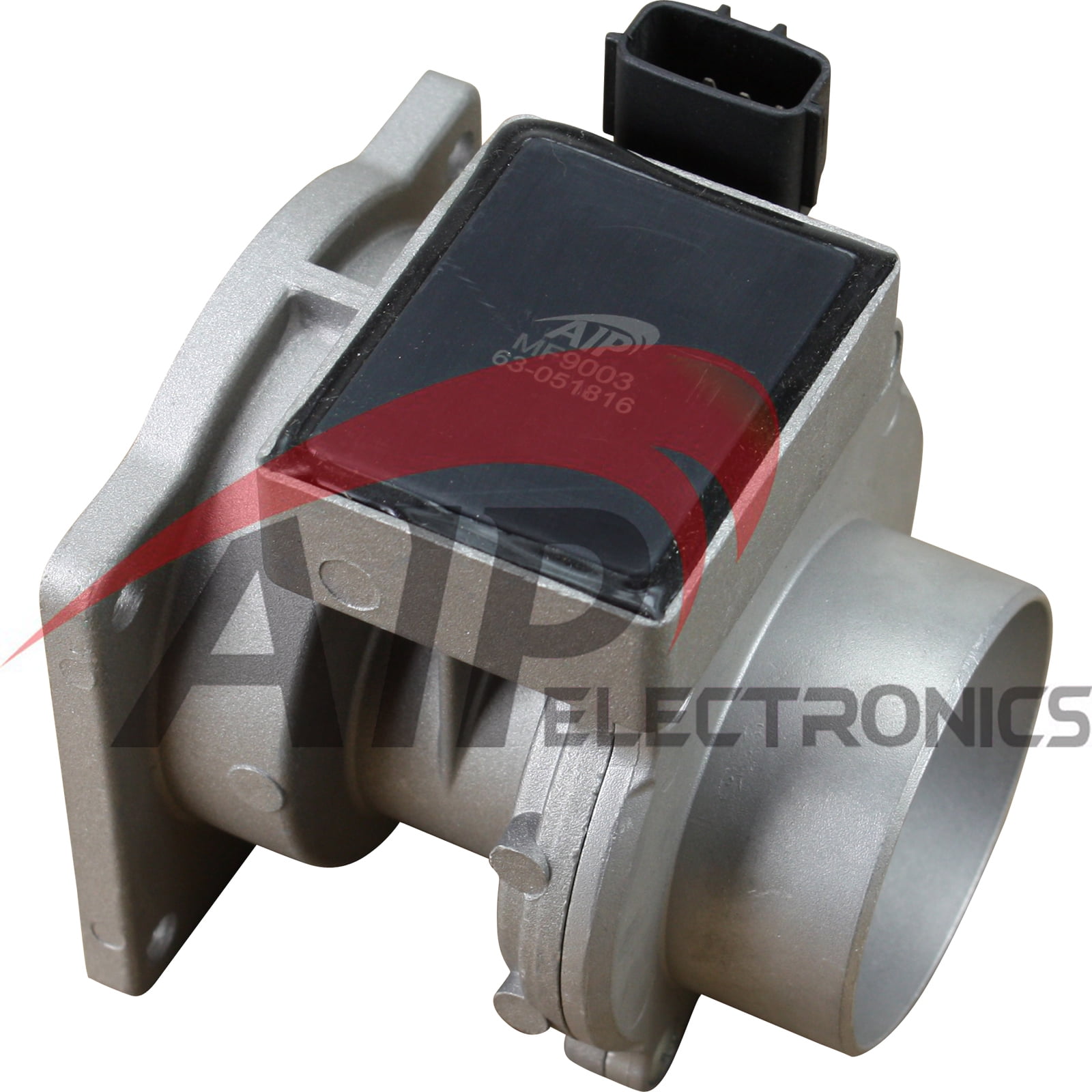
So the signal wire should not reflect a change. The wheatstone bridge would be balanced if you give it 14V, 13V, 12V, 11V, etc.up to a certain point basically. The MAF hot-film and temp sensor is basically a wheatstone bridge coupled with some Op Amps for sensing. The MAF signal wire should be the place to wire the 'trick'. So you'll have to cut that power source ONLY to the wire that feeds the MAF or you stand a good chance it'll affect the camshaft sensor, among some other stuff.Īnother thing, I don't quite get why the MAF power line is used for all this. The actual MAF power comes directly from the ECM relay, which also feeds the distributor camshaft sensor, by the way. I think buying one from Alldata might show me what I need but that costs money.Ĭan I make a few corrections? Ok, thanks.įirst off, Pin 49 is not used to power the MAF. If anyone has a better ECM pinout, I'd love to see it. Also, the Haynes doesn't tell me the pin number of each wire going to the ECU it just shows a bunch of lines going to a box labeled "ECM." Very helpful. My Haynes manual is slightly confusing since, first of all, the vref and ground wires to the connector are the same color :banghead:, and secondly the wiring diagram only refers to wire colors, not their function. I'd like to work from the ECU inside the car as opposed to running two wires from under my hood from the sensor into the car to the switch. I need to cut the voltage source wire going to the sensor and run it through a circuit to allow adjustments.Īnd it shows the ground and signal pins for the MAF but it doesn't specify which pin is the vref. I'm looking to make a MAF adjustment circuit for my car to turn down it's lean limits and allow some other tricks to give me the mileage they have the potential for.


 0 kommentar(er)
